| |
|
| |
Physical simulation |
|
| |
Store Visualizer comes with a physical simulation module which allows you to simulate collisions and the application of physical forces onto your products. Amongst others, it can be used to interactively visualize shelf placement constraints or gravity feed shelving systems. Depending on the complexity of the projects, you will assign the physical simulation to the entire scene or to a selection of products. |
|
| |
|
| |
| |
 |
| |
|
01 |
02 |
03A |
03B |
04 |
05 |
| |
|
|
|
|
|
|
|
|
| |
01. Enable the Physics toolbar by clicking on the Physics icon located on the bottom panel bar.
02. The Start/Stop button controls the current status of the simulation. Press Start to run the simulation, and Stop to interrupt it. Some example projects coming with Store Visualizer do not enable the simulation by default. You will have to start it manually by pressing Start.
By default once the simulation is running, all objects placed within the environment will be subject to physical laws. This is indicated by the message Physics will affect the entire scene. They will collide with other objects and will be affected by gravity and other external forces. Objects that were placed in an unstable position will slide, roll or fall. If you are working on a project with a very large number of products or your computer is not very powerful, you can assign the physical simulation to a specific part of the scene. |
|
| |
|
| |
Simulating physics on part of the scene
03A. You can assign the physical simulation to a specific part of the scene such as a display space, a shelf, a rack, a tray, a POS or similar (partial simulation).
Step 1: Select the 3D objects to which you wish to apply the physical simulation. Then click the Simulate all currently selected objects icon. The message Physics will affect parts of the scene appears.
To assign the physical simulation to all the products present on a shelf, on a rack or in a display space, you must first change construction mode to select the shelf, rack or display space to which you want to assign the simulation. Once you have selected it, click the Simulate all currently selected objects icon. Return to product mode (F2) to proceed to step 2.
Step 2: Press the Start icon to activate the simulation. The message Physics is running on parts of the scene appears. All products selected in step 1 will be affected by the physics. Press the Stop icon to interrupt the simulation.
| |
|
| |
 |
| |
|
|
|
03A |
|
|
Simulating physics on the entire scene
03B. When the physical simulation is running on part of the scene (see 03A) and you want the entire scene to be affected, click the Simulate the entire scene icon. The current physical simulation process will stop automatically. Press the Start icon again to start the simulation.
By default, the physical simulation will always affect the entire scene. |
|
| |
|
| |
|
| |
Moving objects with physics |
|
| |
| |
|
|
|
| |
 |
You can interact with objects under physical simulation the same way you learned in the previous sections. However when a simulation is running, a number of physical restrictions apply. You may not push an object through a shelf panel or another object, for example.
While you are moving or rotating an object, certain physical laws are temporarily disabled. This makes it easier to manipulate the object. Once you stop interacting with it, by releasing the left mouse button, all physical laws come back into effect. For example, you might move a product out of a shelf, holding it floating in the air. Once you release the mouse button, gravity will make it fall down.
04. The Toggle between physics or conventional mode button selects how collisions between the object and the environment are handled. If pressed, collisions will fully apply, and the movement of the object will be limited by the environment. If not pressed, then the environment will not block the object, and you will be able to move it through walls, for example. It is usually advised to keep this button pressed, since the movements are more physically correct that way. |
|
|
| |
|
| |
|
| |
Dragging an object |
|
| |
|
| |
| |
 |
Dragging is an alternative mode of moving an object. It is only available while a physical simulation is running.
It works by grabbing the object at a point, and pulling it as if it was attached to a rubber band. Dragging is a very flexible mode of interaction, and it is the most physically correct. All physical properties are taken into account while dragging, including mass, momentum and friction.
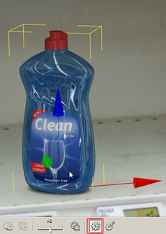
05. Enable dragging mode by pressing the Drag object icon. Now click on the object you would like to move at the point you would like to attach the virtual rubber band. Hold the left mouse button and move the object.
If you press the Ctrl key while still holding the left mouse button, you may move the object up and down. Without the Ctrl key pressed, your movements will be on a horizontal plane.
|
|
|
| |
|
| |
|
| |
Physical properties |
|
| |
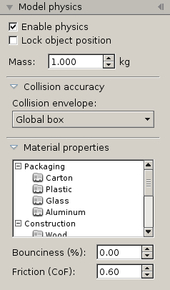
In order to react realistically, the simulator needs to know about a number of physical properties, such as the models weight and surface. These properties are defined in the Model Physics panel, located on the Tools Sidebar. |
|
| |
| |
|
The panel shows all properties for the currently selected model. Please consult the Placing Products section for a reminder on how to select a model from a library.
Weight
An important parameter is the weight. Heavier objects will have more momentum when they collide with other objects, and they will require a larger force in order to be moved. The default mass is 1kg (2,2lb).
Material properties
Use the Material properties section to assign a certain surface material to your model. The surface type will change the way objects react when they are in contact with other surfaces or objects. A rough surface material such as cardboard is less likely to slide (it has higher friction) than a smooth plastic surface, for example.
Note: changing surface material will only affect the way a model reacts in the physical simulation. It will not change its visual aspect. |
|
|
| |
|
| |
|
| |
Collision accuracy |
|
| |
The physics simulator typically uses an approximate shape representing the object so to increase the performance of the simulation. The collision accuracy section allows you to control the precision of this shape. The default accuracy, global envelope, is appropriate for most packaging models or consumer products. If however your model contains large cavities in which other objects are placed into (for example a tray or a display), then the default mode is not appropriate anymore. The shape would cover the cavities and you would not be able to place any objects into them. For such models, select the decomposed envelopes mode or the planar envelopes mode.
When an object is frozen in the scene, it will automatically have a highly accurate collision envelope. |
|
| |
|
| |
Collision envelope - Global box |
|
| |
| |
|
|
|
| |
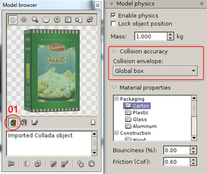 |
The accuracy of collisions between the 3D models will depend on the collision envelope that you have allocated to each of your models. The physical simulation model offers you four types of collision envelope. You have to select the collision envelope suitable for the physical simulation to run optimally.
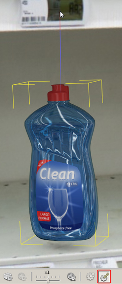
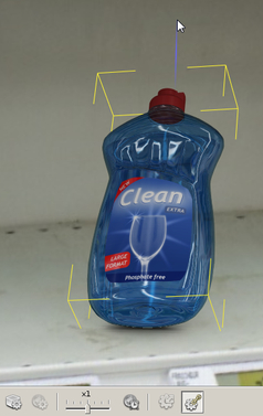
01. Press the Show model with collision envelope button to display the model together with its physics envelope.
Global box: this mode approximates the objects’ shape with a box. This is a very high performance mode, and is ideally suited for models that have an inherently box-like shape. If applied to models that are not box-shaped, this mode may generate visual errors in the physical simulation. |
|
|
| |
|
| |
|
| |
Collision envelope - Global envelope |
|
| |
| |
|
|
|
| |
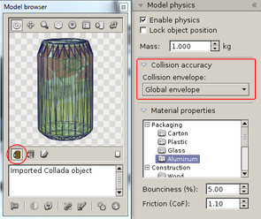 |
Global envelope: this mode fits a convex skin around the model, following its outline as close as possible. The global envelope mode achieves both good performance and fits models with arbitrary shapes.
As such, it is a good default choice for most non-box shaped products. This mode cannot be used with hollow models containing other objects (such as trays, hollow boxes or displays, for example). The envelope will cover the cavity and you will not be able to place objects inside it.
|
|
|
| |
|
| |
|
| |
Collision envelope - Decomposed envelopes |
|
| |
| |
|
|
|
| |
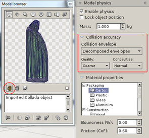 |
Decomposed envelopes: this mode can fit a model very closely by using a combination of multiple convex envelopes and thus allows a very precise simulation. It should be used for models featuring large cavities.
Quality: quality of the decomposed envelope.
Concavities: detail level for the decomposition of cavities.
Decomposed envelopes require high performance and may therefore significantly slow down the physical simulation if there are too many of them. We advise you to only activate this type of envelope if the envelopes above do not generate the required quality. |
|
|
| |
|
| |
|
| |
Collision envelope - Planar envelopes |
|
| |
| |
|
|
|
| |
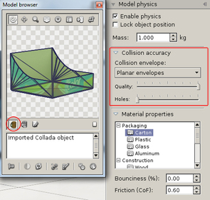 |
Planar envelopes are used in models consisting of hollows or individual planar elements, such as cardboard panels or metal sheets. Planar mode was specifically designed for use with trays, displays and similar models.
Planar mode does not work with models not made of distinct planar elements. In this case, the decomposed envelopes settings should be used instead.
Quality: Quality of the planar envelope. The further you drag the slider to the right, the higher the quality of the planar decomposition will be.
Holes: Minimal area of holes to be decomposed. The further you drag the slider to the right, the more you decompose the holes present in your model.
|
|
|
| |
|
| |
|
| |
|
| |
|
|
|
© Copyright 2018 VTales graphics - All rights reserved.
|

